
Views: 0 Author: Site Editor Publish Time: 2026-07-28 Origin: Site


In precision automation and motion control, achieving exact positioning often forces engineering teams into a difficult compromise between system complexity, integration time, and overall hardware costs. Defaulting to complex closed-loop servo systems for every application leads to over-engineering, inflating the Bill of Materials and requiring extensive tuning. Conversely, under-engineering the drive mechanism risks catastrophic positioning errors and machine downtime. For applications requiring high repeatability and stability under predictable loads, stepper motors offer a highly efficient alternative. This guide examines the technical and commercial stepper motor advantages, providing a framework for evaluating when to specify them over competing motion control technologies. We will look at the mechanical realities of open-loop systems, torque curves, and thermal management to help you make informed specification decisions on the factory floor.
Simplified Architecture: Open-loop operation eliminates the need for expensive position feedback sensors and complex tuning algorithms, drastically reducing integration time and upfront costs.
Low-Speed Power: Stepper motors deliver their maximum torque at low speeds, often eliminating the need for external gearboxes in direct-drive applications.
Inherent Load Stability: Constant holding torque ensures the motor locks into position without the "hunting" or micro-jittering common in servo systems.
Design Trade-offs: Maximizing these benefits requires strict adherence to proper motor sizing, drive circuitry selection, and thermal management to mitigate inherent risks like resonance, heat generation, and missed steps.
Table of Contents
Establish the baseline requirements for the application, focusing on required resolution, speed profiles, load predictability, and acceptable error margins. Understanding these parameters helps determine if the inherent characteristics of a stepper motor align with the project goals. Precision positioning requires a clear definition of what constitutes an acceptable deviation from the target. You must measure the exact payload mass, the required travel distance, and the acceptable settling time. If the load remains constant and the speed requirements stay below 1,000 RPM, you are looking at a prime candidate for stepper technology. Engineers often make the mistake of specifying motors based on peak theoretical performance rather than actual application demands. By mapping out the exact motion profile, you avoid paying for dynamic response capabilities you will never use.
Analyze the hidden costs of closed-loop systems, such as cabling, encoder fragility, and PID tuning time, in applications where load dynamics do not strictly require continuous feedback correction. Using a complex servo system when a simpler solution suffices increases both upfront hardware costs and long-term maintenance requirements. Every additional sensor introduces a new potential point of failure. In environments with high vibration or particulate contamination, optical encoders often fail long before the motor windings degrade. Furthermore, the engineering hours spent tuning PID loops to eliminate resonance can derail project timelines. When you eliminate the feedback loop, you strip away layers of complexity. This streamlined approach directly translates to faster commissioning and fewer maintenance calls from the field.
Stepper motors leverage high pole counts to overcome static friction when starting heavy loads from a standstill. This capability allows them to initiate movement without the instability or overshoot common to tuned servo loops. The high initial torque is a critical factor in applications requiring precise movement of heavy components. When a machine sits idle, lubricants settle and mechanical components bind slightly. Breaking this static friction, or stiction, requires a massive spike in torque. Because steppers operate at full current even at zero speed, they deliver maximum rotational force the instant the first step pulse arrives. This brute-force starting capability makes them highly effective for driving lead screws, heavy indexing tables, and conveyor belts where the initial breakaway force significantly exceeds the continuous running force.
Define the ideal operational envelope for steppers: low-to-medium speeds, highly predictable loads, and environments where holding a static position is critical. When operating within these parameters, stepper motors provide reliable and cost-effective motion control. Understanding this sweet spot ensures optimal system performance. The ideal application involves short, rapid indexing movements followed by extended dwell times. Think of pick-and-place machines, 3D printer extruders, and automated fluid dispensing systems. In these scenarios, the motor must move to a specific coordinate, stop instantly, and hold that position with absolute rigidity while another operation occurs. If your application fits this profile, the mechanical and electrical characteristics of a stepper motor will outperform more complex alternatives.
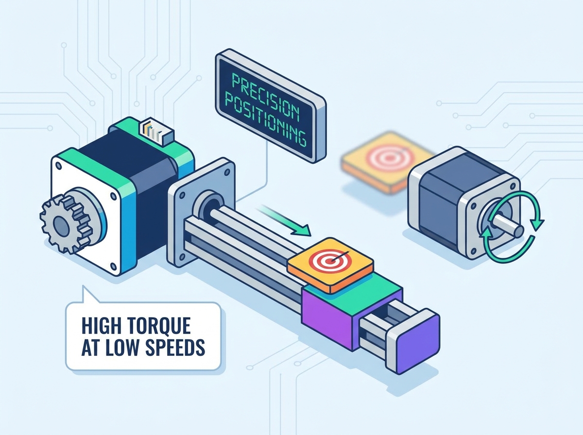
Stepping in discrete magnetic increments allows the controller to track position by simply counting pulses. This method bypasses the need for optical encoders or resolvers, simplifying the overall system architecture. The reduction in components leads to lower costs and fewer potential points of failure. You send 200 pulses to a standard 1.8-degree stepper, and the shaft rotates exactly one revolution. The controller assumes the motor executed the command, provided the load did not exceed the available torque. This open-loop architecture means you only need two wires for power and a few wires for the step and direction signals. You do not have to route delicate encoder cables back to the drive, shielding them from electromagnetic interference along the way. This simplicity is one of the most significant stepper motor advantages for machine builders looking to streamline their electrical panels.
The magnetic pole density of stepper motors translates to massive low-end rotational force and high initial acceleration rates. This characteristic makes them ideal for starting heavy loads or driving lead screws. A standard hybrid stepper motor contains 50 teeth on the rotor and corresponding teeth on the stator poles. This high tooth count creates a very tight magnetic coupling. When the coils energize, the magnetic flux pulls the rotor teeth into alignment with immense force. This design generates significantly more torque at low speeds than a similarly sized servo motor. You can often connect the motor shaft directly to the load, eliminating the backlash, maintenance, and cost associated with planetary gearboxes. Direct-drive configurations improve overall system stiffness and positioning accuracy.
Stepper motors draw full current at a standstill, allowing them to act as a dynamic brake and hold payloads rigidly in place without mechanical clamping. This constant holding torque enables exceptional design flexibility across diverse positioning setups. The motor maintains its position firmly, resisting external forces. If a machining operation applies lateral force to a linear stage, the stepper motor resists that force up to its rated holding torque limit. Servo motors, by contrast, rely on error signals to generate holding torque. They must detect a slight movement away from the target position before they apply corrective force, resulting in a microscopic oscillation known as hunting. Steppers lock into the magnetic detent and remain absolutely stationary, making them superior for vision inspection systems and laser cutting applications where any vibration ruins the process.
Contrast simple step/direction pulse generation with the complex PID loop tuning, external feedback wiring, and proprietary software required for servo drives. The straightforward control mechanism of stepper motors highlights the reduction in engineering setup hours. Commissioning a stepper system is generally faster and less resource-intensive. You set the current limit via a dip switch on the drive, connect the phase wires, and start sending pulses from the PLC. There is no need to run auto-tuning routines, adjust proportional gains, or filter out resonance frequencies in software. This plug-and-play nature drastically reduces the time required to get a new machine up and running. It also simplifies field replacements. If a drive fails, a maintenance technician can swap it out and set the dip switches without needing a laptop or specialized software.
Highlight the non-cumulative nature of step errors, typically 3-5% per step, ensuring exact return-to-zero capabilities over millions of cycles. This predictability is crucial for applications requiring consistent and accurate positioning over extended periods. The inherent repeatability minimizes the need for frequent recalibration. If a motor has a 5% step error, that error applies only to the current step. It does not compound as the motor continues to rotate. After 10,000 revolutions, the motor will return to its exact starting position with the same 5% tolerance on the final step. This mechanical absolute positioning ensures that long-running automated processes do not drift out of alignment over time. You can rely on the machine to hit the same coordinates on day 100 as it did on day one.
Break down the Bill of Materials reduction, including fewer cables, cheaper drives, and no encoders, and the reduction in engineering hours due to the absence of control loop tuning. The economic benefits of stepper motors make them an attractive option for many projects. Evaluating the cost-to-performance ratio helps justify the selection of stepper technology. When you factor in the cost of the motor, the drive, the cables, and the engineering time, a stepper system often comes in at a fraction of the cost of a comparable servo system. This cost advantage becomes even more pronounced in multi-axis machines where the savings multiply across every joint. You can allocate the saved budget to other critical areas of the machine design, such as better linear guides or higher-quality tooling.
Direct application of stepper motors in linear, rotary, and multi-axis stages is common for optical alignments, microscopy, and laboratory automation where step repeatability is paramount. These applications benefit significantly from the precise control offered by stepper motors. The integration process is straightforward due to the simplified control architecture. When driving a ball screw, the discrete steps of the motor translate into precise linear increments. By selecting a screw with an appropriate pitch, you can achieve sub-micron resolution without needing linear encoders. This mechanical gearing effect, combined with the motor's inherent repeatability, provides a highly stable platform for sensitive instrumentation. The lack of hunting ensures that optical lenses or probes remain perfectly still during measurement cycles.

Evaluate the ease of daisy-chaining stepper drives and synchronizing multiple axes in applications like 3D printing, CNC machining, and automated optical inspection stages. The ability to easily scale the system is a significant advantage. Multi-axis coordination is achievable without complex networking protocols. Most basic PLCs and microcontrollers can generate multiple step and direction signals simultaneously. You do not need expensive motion controllers with EtherCAT or PROFINET capabilities to synchronize three or four axes. This makes steppers the go-to choice for desktop manufacturing equipment and custom automation cells. You can easily add an additional axis to a machine by simply wiring in another low-cost drive and assigning a new output channel on the controller.
Examine standard NEMA frame sizing, ruggedness due to the lack of fragile feedback electronics, and considerations for IP-rated enclosures in harsh industrial environments. Stepper motors are robust and can operate reliably in challenging conditions. The absence of delicate sensors enhances their durability. The standardized NEMA frame sizes (such as NEMA 17, 23, and 34) mean you can easily source replacement motors from multiple vendors without redesigning your mounting brackets. Because the motor consists primarily of copper windings and iron laminations, it can withstand significant physical shock and vibration. For washdown environments or areas with heavy dust, you can specify IP65-rated steppers that seal the internal components against ingress, ensuring long-term reliability in less-than-ideal conditions.
Feature | Stepper Motor | Servo Motor |
|---|---|---|
Control Architecture | Open-loop (Pulse/Direction) | Closed-loop (Encoder Feedback) |
Low-Speed Torque Delivery | Maximum torque at standstill | Requires gearing for high low-end torque |
High-Speed Performance | Torque drops off rapidly above 1000 RPM | Maintains flat torque curve at high RPM |
Position Holding | Absolute rigidity (No hunting) | Micro-oscillations (Hunting) |
Wiring Complexity | 4 to 6 wires total | Power cables plus multi-wire encoder cables |
Analyze the torque curve degradation and reduced acceleration capability at higher RPMs due to winding inductance and back electromotive force. Establishing clear speed limits for stepper viability is essential to prevent performance issues. Operating beyond these limits can result in a loss of synchronization. As the motor spins faster, the time available to push current into the inductive windings decreases. Simultaneously, the spinning rotor generates a back EMF voltage that opposes the drive voltage. This combination chokes off the current, causing the available torque to plummet. If you try to accelerate a load while operating in this high-speed, low-torque region, the motor will stall. You must carefully consult the manufacturer's pull-out torque curve to ensure your application stays within the safe operating area.
Address the fact that traditional steppers run at full current regardless of load demand, leading to significant heat generation during normal use. This requires heatsinking or active cooling to maintain optimal operating temperatures. Proper thermal management extends the lifespan of the motor and drive circuitry. Because the drive constantly pumps maximum rated current through the coils to maintain holding torque, the motor acts like a space heater. Surface temperatures can easily exceed 80 degrees Celsius during continuous operation. You must design your mounting brackets to act as heat sinks, drawing thermal energy away from the motor case. In enclosed spaces, you may need to add cooling fans to prevent the internal insulation from degrading over time.
Unpredictable load spikes or mechanical binding can cause a loss of synchronization between the stator field and rotor. This results in unrecorded position loss in open-loop setups. Mitigating this risk requires careful sizing and load management. If a tool crashes or a bearing seizes, the load exceeds the motor's torque capacity. The magnetic field continues to rotate, but the rotor stalls. Because there is no encoder to report this failure, the controller continues to send pulses, assuming the motor is moving. The machine loses its coordinate system, leading to scrapped parts or further mechanical damage. You must design the system with sufficient torque margins to handle worst-case friction and acceleration loads.
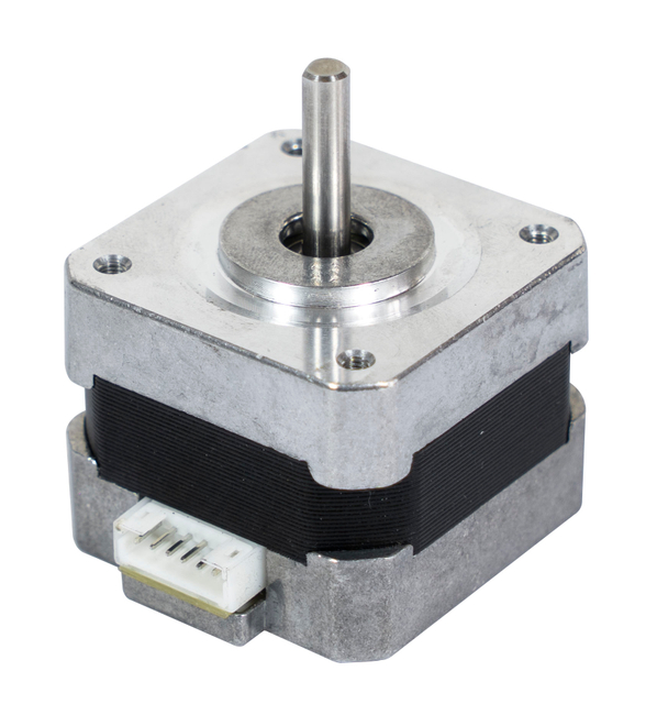
Leverage chopper drives and constant-current drivers to maintain torque at higher speeds while managing thermal output and motor efficiency. Advanced drive circuitry significantly improves overall system performance. Proper current control reduces heat generation and extends motor life. Modern chopper drives use high bus voltages (often 48V or 72V) to force current into the windings rapidly, overcoming the inductance limitations at higher speeds. Once the current reaches the target level, the drive rapidly switches the voltage on and off (chopping) to maintain a constant current. Many drives also feature an idle current reduction setting. This automatically drops the holding current by 50% when the motor stops moving, drastically reducing heat generation without sacrificing position stability.
Modern drive circuitry subdivides fundamental steps to smooth out low-speed resonance, reduce acoustic noise, and increase positioning resolution. Microstepping enhances the smoothness of motion and improves accuracy. This technique is crucial for applications requiring high precision. A standard motor has 200 full steps per revolution. By proportioning the current between the two motor phases, a microstepping drive can create intermediate magnetic holding positions. Setting the drive to 16 microsteps per full step yields 3,200 steps per revolution. This eliminates the harsh, jerky movements associated with full-stepping at low speeds. It also pushes the motor's natural resonance frequency out of the typical operating range, preventing severe vibration and stalling.
Provide the engineering best practice of over-sizing stepper motors by 30-50% above the calculated peak load, combined with proper load-to-rotor inertia matching. This guarantees step integrity under worst-case scenarios. Proper sizing is the most effective way to prevent missed steps. You calculate the torque required to accelerate the load, overcome friction, and perform the work. Then, you multiply that figure by 1.5. This safety margin accounts for manufacturing tolerances, bearing wear over time, and unexpected variations in the payload. Additionally, you must ensure the inertia of the load does not exceed the inertia of the rotor by more than a 10:1 ratio. High inertia mismatches cause the motor to overshoot its target position and lose synchronization during deceleration.
Introduce the modern compromise of adding an encoder to a stepper motor, combining the low-cost, high-torque benefits of a stepper with the error-correction and demand-based current capabilities of a servo. Closed-loop steppers offer a middle ground for applications requiring feedback without the full cost of a servo system. These systems monitor the encoder position and adjust the current dynamically based on the actual load. If the motor encounters a mechanical obstruction, the drive increases the current to push through it. If the error becomes too large, the drive faults out and alerts the controller, preventing catastrophic position loss. This hybrid approach provides the low-speed torque and stability of a stepper with the reliability of a closed-loop system.
The stepper motor advantages make stepper motors an excellent choice for applications requiring precise positioning, high holding torque, simple integration, and predictable load conditions. Selecting the right motor, driver, and control strategy helps maximize system reliability while reducing engineering complexity and overall project costs.
About Ritscher
Ritscher is a professional manufacturer of motion control solutions, offering high-quality stepper motors, servo motors, brushless DC motors, gear motors, and customized drive systems for industrial automation and OEM applications. With advanced manufacturing capabilities and years of engineering experience, Ritscher delivers reliable, energy-efficient products that help customers achieve precise and dependable motion control.
Select a stepper motor based on actual load, speed, and positioning requirements.
Match the driver, power supply, and transmission system for optimal performance.
Apply proper torque safety margins and thermal management to improve reliability.
Consider closed-loop stepper solutions when additional feedback and protection are required.
Before choosing a stepper motor, carefully evaluate your application's load characteristics, operating speed, positioning accuracy, installation environment, and future expansion needs to achieve the best long-term performance and value.
A: The primary advantages include lower upfront hardware costs, simplified open-loop control that eliminates complex PID tuning, massive torque generation at low speeds, and absolute holding rigidity at a standstill without hunting.
A: Stepper motors utilize a high pole count and tight magnetic coupling between the rotor and stator teeth. This design allows them to generate significant magnetic force and rotational torque even at low RPMs or when starting from a standstill.
A: Stepper motors offer rapid initial acceleration due to their high low-end torque. However, their acceleration capability drops off significantly at higher speeds due to winding inductance, whereas servo motors maintain a flatter torque curve.
A: Advanced drive circuitry, such as high-voltage chopper drives and microstepping controllers, forces current into the windings faster to maintain torque at higher speeds, reduces mechanical resonance, and improves overall positioning resolution.
A: No, standard stepper motors operate in an open-loop system. The controller tracks position by counting the discrete input pulses sent to the drive, eliminating the need for external feedback sensors like optical encoders.
A: You prevent lost steps by over-sizing the motor by 30-50% above the calculated peak load, ensuring proper load-to-rotor inertia matching, and utilizing acceleration ramps to avoid unpredictable load spikes or mechanical binding.